Engineering Mechanics: Statics and Dynamics, 14th Edition
Authors: Russell C. Hibbeler
ISBN-13: 978-0133915426
See our solution for Question 22P from Chapter 19 from Hibbeler's Engineering Mechanics.
Problem 22P
Step-by-Step Solution
We have given the following values:
The weight of gear A is ${W_A} = 15\;{\rm{lb}}$.
The radius of gyration of gear A is ${k_A} = 0.5\;{\rm{ft}}$.
The weight of gear B is ${W_B} = 10\;{\rm{lb}}$.
The radius of gyration of gear B is ${k_B} = 0.35\;{\rm{ft}}$.
The radius gear A is ${r_A} = 0.8\;{\rm{ft}}$.
The radius gear B is ${r_B} = 0.5\;{\rm{ft}}$.
The moment acting on gear B is $M = 2\left( {1 - {e^{ - 0.5t}}} \right)\;{\rm{lb}} \cdot {\rm{ft}}$.
We are asked to calculate the angular velocity of gear A in time $t = 5\;{\rm{s}}$.
Step 2
Let ${\omega _A}$ is the angular velocity of gear A and ${\omega _B}$ is the angular velocity of gear B.
The relation between the angular velocities of the two gears is given by:
\[{\omega _A}{r_A} = {\omega _B}{r_B}\]Substitute the value of ${r_A}$ and ${r_B}$ in the above equation:
\[\begin{array}{c} {\omega _A}\left( {0.8\;{\rm{ft}}} \right) = {\omega _B}\left( {0.5\;{\rm{ft}}} \right)\\ {\omega _B} = 1.6{\omega _A} \end{array}\]Step 3
Draw the labeled free body diagrams of the gears.
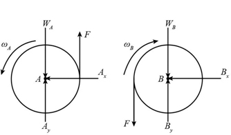
Here, ${A_x}$ and ${A_y}$ are the horizontal and vertical reaction force acting at gear A, ${B_x}$ and ${B_y}$ are the horizontal and vertical reaction force acting at gear B, and $F$ is the force applied by the gears at point of contact.
Step 4
Consider gear B and apply the principle of impulse and momentum about the center of gear B:
\[\begin{array}{c} {\left( {{H_B}} \right)_1} + \sum {\int {{M_B}dt} } = {\left( {{H_B}} \right)_2}\\ 0 + \int\limits_0^5 {2\left( {1 - {e^{ - 0.5t}}} \right)dt} - \int {{r_B}Fdt} = \left[ {\left( {\frac{{{W_B}}}{g}} \right)k_B^2} \right]{w_B} \end{array}\]Substitute the value of parameters in the above equation:
\[\begin{array}{c} 0 + \int\limits_0^5 {2\left( {1 - {e^{ - 0.5t}}} \right)dt\;{\rm{lb}} \cdot {\rm{ft}}} - \int {\left( {0.5\;{\rm{ft}}} \right)Fdt} = \left[ {\left( {\frac{{10\;{\rm{lb}}}}{{32.2\;{\rm{ft}}/{{\rm{s}}^2}}}} \right){{\left( {0.35\;{\rm{ft}}} \right)}^2}} \right]\left( {1.6{\omega _A}} \right)\\ 6.328\;{\rm{lb}} \cdot {\rm{ft}} - \int {\left( {0.5\;{\rm{ft}}} \right)Fdt} = 0.06087{\omega _A}\;{\rm{lb}} \cdot {\rm{ft}}/{{\rm{s}}^2}\\ \int {\left( {0.5\;{\rm{ft}}} \right)Fdt} = 6.328\;{\rm{lb}} \cdot {\rm{ft}} - 0.06087{\omega _A}\;{\rm{lb}} \cdot {\rm{ft}}/{{\rm{s}}^2}\\ \int {Fdt} = \frac{{6.328\;{\rm{lb}} \cdot {\rm{ft}} - 0.06087{\omega _A}\;{\rm{lb}} \cdot {\rm{ft}}/{{\rm{s}}^2}}}{{\left( {0.5\;{\rm{ft}}} \right)}} \end{array}.\].....(1)Step 5
Consider gear A and apply the principle of impulse and momentum about the center of gear A:
\[\begin{array}{c} {\left( {{H_A}} \right)_1} + \sum {\int {{M_A}dt} } = {\left( {{H_A}} \right)_2}\\ 0 + \int {{r_A}Fdt} = \left[ {\left( {\frac{{{W_A}}}{g}} \right)k_A^2} \right]{w_A} \end{array}\]Substitute the value of parameters in the above equation:
\[\begin{array}{c} 0 + \int {\left( {0.8\;{\rm{ft}}} \right)Fdt} = \left[ {\left( {\frac{{15\;{\rm{lb}}}}{{32.2\;{\rm{ft}}/{{\rm{s}}^2}}}} \right){{\left( {0.5\;{\rm{ft}}} \right)}^2}} \right]{\omega _A}\\ 0 + \int {\left( {0.8\;{\rm{ft}}} \right)Fdt} = 0.1165{\omega _A}\;{\rm{lb}} \cdot {\rm{ft}}/{{\rm{s}}^2}\\ \int {Fdt} = \frac{{0.1165{\omega _A}\;{\rm{lb}} \cdot {\rm{ft}}/{{\rm{s}}^2}}}{{\left( {0.8\;{\rm{ft}}} \right)}} \end{array}.\].....(2)Step 6
On comparing equation (1) and (2), we get:
\[\begin{array}{c} \frac{{6.328 - 0.06087{\omega _A}}}{{0.5}} = \frac{{0.1165{\omega _A}}}{{0.8}}\\ {\omega _A} = 47.3\;{\rm{rad}}/{\rm{s}} \end{array}\]