Engineering Mechanics: Statics and Dynamics, 14th Edition
Authors: Russell C. Hibbeler
ISBN-13: 978-0133915426
See our solution for Question 1PP from Chapter 6 from Hibbeler's Engineering Mechanics.
Problem 1PP
Step-by-Step Solution
We are given two trusses each of which is supported by a pin and a roller support.
We are asked to calculate the reaction forces at supports and draw the free-body diagrams of joint A, B, and C.
Step 2
Part (a)
Draw a free-body diagram of the truss.
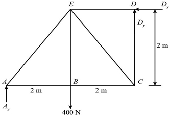
Here, ${A_y}$ is the reaction force at point A, ${D_x}$ is the horizontal reaction force at support D, and${D_y}$ is the vertical reaction force at support D.
Apply equilibrium equation for the moment about point D:
\[\begin{array}{c} \sum {{M_D}} = 0\\ - {A_y} \times 4\;{\rm{m}} + 400\;{\rm{N}} \times 2\;{\rm{m}} = 0\\ {A_y} = \frac{{400\;{\rm{N}} \times 2\;{\rm{m}}}}{{4\;{\rm{m}}}}\\ {A_y} = 200\;{\rm{N}} \end{array}\]Apply equilibrium equation of the forces in the horizontal direction:
\[\begin{array}{c} \sum {{F_x}} = 0\\ {D_x} = 0 \end{array}\]Apply equilibrium equation of the forces in the vertical direction:
\[\begin{array}{c} \sum {{F_y}} = 0\\ {A_y} + {D_y} - 400\;{\rm{N}} = 0\\ {D_y} = 400\;{\rm{N}} - {A_y} \end{array}\]Substitute the value of ${A_y}$ in the above equation:
\[\begin{array}{c} {D_y} = 400\;{\rm{N}} - 200\;{\rm{N}}\\ = 200\;{\rm{N}} \end{array}\]Consider each member in tension.
Draw a free-body diagram of joint A.
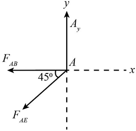
Here, ${F_{AB}}$ and ${F_{AE}}$ are the forces in member AB and AE.
Draw a free-body diagram of joint B.
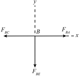
Here, ${F_{BA}}$ is the force in member AB, ${F_{BC}}$ is the force in member BC, and ${F_{BE}}$ is the force in member BE.
Draw a free-body diagram of joint C.
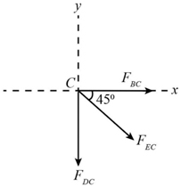
Here, ${F_{BC}}$ is the force in member BC, ${F_{DC}}$ is the force in member DC, and ${F_{EC}}$ is the force in member EC.
Step 3
Part (b)
Draw a free-body diagram of the truss.
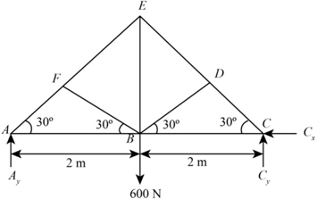
Here, ${A_y}$ is the reaction force at point A, ${C_x}$ is the horizontal reaction force at support C, and ${C_y}$ is the vertical reaction force at support C.
Apply equilibrium equation for the moment about point C:
\[\begin{array}{c} \sum {{M_C}} = 0\\ - {A_y} \times 4\;{\rm{m}} + 600\;{\rm{N}} \times 2\;{\rm{m}} = 0\\ {A_y} = \frac{{600\;{\rm{N}} \times 2\;{\rm{m}}}}{{4\;{\rm{m}}}}\\ {A_y} = 300\;{\rm{N}} \end{array}\]Apply equilibrium equation of the forces in the horizontal direction:
\[\begin{array}{c} \sum {{F_x}} = 0\\ {C_x} = 0 \end{array}\]Apply equilibrium equation of the forces in the vertical direction:
\[\begin{array}{c} \sum {{F_y}} = 0\\ {A_y} + {C_y} - 600\;{\rm{N}} = 0\\ {C_y} = 600\;{\rm{N}} - {A_y} \end{array}\]Substitute the value of ${A_y}$ in the above equation:
\[\begin{array}{c} {C_y} = 600\;{\rm{N}} - 300\;{\rm{N}}\\ = 300\;{\rm{N}} \end{array}\]Consider each member in the tension.
Draw a free-body diagram of point A.
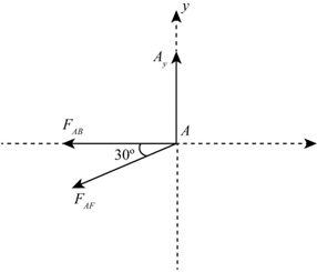
Here, ${F_{AF}}$ is the force in member AF, ${F_{AB}}$ is the force in member AB.
Draw a free-body diagram of joint B.
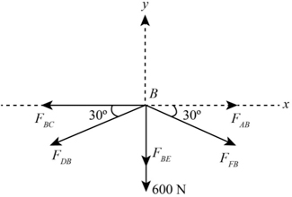
Here, ${F_{AB}}$ is the force in member AB, ${F_{FB}}$ is the force in member FB, ${F_{BE}}$ is the force in member BE, ${F_{DB}}$ is the force in member DB, and ${F_{BC}}$ is the force in member BC.
Draw a free-body diagram of joint C.
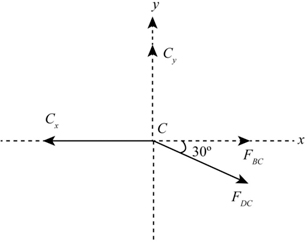
Here, ${F_{DC}}$ is the force in member DC, and${F_{BC}}$ is the force in member BC.