Engineering Mechanics: Statics and Dynamics, 14th Edition
Authors: Russell C. Hibbeler
ISBN-13: 978-0133915426
See our solution for Question 3PP from Chapter 6 from Hibbeler's Engineering Mechanics.
Problem 3PP
Step-by-Step Solution
We are given the different types of frames in each case.
We are asked to identify any two-force members and also to draw the free-body diagram of each member of the frame.
Step 2
For satisfying the condition of two-force members, three points must be followed as:
1. At maximum there are two applied forces which must be equal in magnitude and opposite in direction.
2. Moment equilibrium should be maintained.
3. The applied forces on a member should be the same line of action.
Part (a)
The free-body diagram of the member AB and BC can be drawn as:
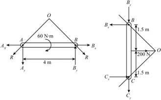
The member AB and BC has the same line of action which meets at point O and the resultant forces at pin joints is R.
For the member AB and BC, asboth has pin joints, each of these members has one resultant reaction at support. Also, both the members have an applied external load at points other than the pin joints. Hence, there are no two force members.
Part (b)
The free-body diagram of the member AB and BC can be drawn as:
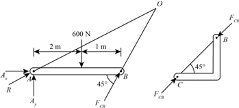
The member AB has three forces such as one resultant force each at A and B and one external load. Hence, the member AB cannot be atwo-force member.
For the member CB, as it has no external load and has a pin support at point C, it produces a reaction equal to the reaction force at joint B. Also, the force at joint B and at the support C are collinear for equilibrium. Hence, the member CB is a two-force member.
Step 3
Part (c)
The free-body diagram of the member AB, BC and CD can be drawn as:

The member AB has three forces such as one resultant force each at A and B and one external moment. Hence, the member AB cannot be a two-force member.
For the member BC, it has also three forces such as one resultant force each at B and C and one external point load. Hence, the member BC cannot be a two-force member.
Similarly, for the member CD, it has two resultant forces, one at joint C and other at support D. Also, it has no external load or moments so, the member CD can be a two-force member.
Part (d)
The free-body diagram of the member AB and BC can be drawn as:
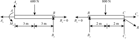
The member AB has three forces such as one resultant force each at A and B and one external point load. Hence the member AB cannot be a two-force member.
Similarly, for the member BC, it has also three forces such as one resultant force each at B and C and one external point load. Hence the member BC cannot be a two-force member.
Part (e)
The free-body diagram of the member AB and BC can be drawn as:
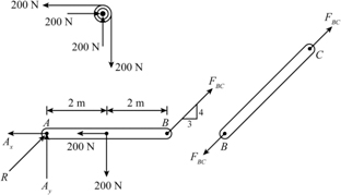
The member AB has more than two forces so, it cannot be a two-force member. Whereas, the member BC has two forces and also has no external load is applied so, the member BC is a two-force member.
Step 4
Part (f)
The free-body diagram of the member AB and BC can be drawn as:

The member AB has more than two forces so, it cannot be a two-force member. Whereas, the member BC has two forces and also has no external load is applied so, the member BC is a two-force member.