Engineering Mechanics: Statics and Dynamics, 14th Edition
Authors: Russell C. Hibbeler
ISBN-13: 978-0133915426
See our solution for Question 46P from Chapter 6 from Hibbeler's Engineering Mechanics.
Problem 46P
Step-by-Step Solution
We are given that force applied at point B is ${F_B} = 4\;{\rm{kN}}$, the force applied at point C is ${F_C} = 8\;{\rm{kN}}$ and the force applied at point D is ${F_D} = 5\;{\rm{kN}}$.
We are asked to calculate the force in members BC, CH, GH and CG of the truss.
We have the angle made by force EB with the horizontal which is $\theta = 45^\circ $.
We have the horizontal distance between points A and B which is ${d_1} = 4\;{\rm{m}}$.
We have the horizontal distance between points B and C which is ${d_2} = 4\;{\rm{m}}$.
We have the horizontal distance between points C and D which is ${d_3} = 4\;{\rm{m}}$.
We have the horizontal distance between points D and E which is ${d_4} = 4\;{\rm{m}}$.
We have the vertical distance between points E and F which is ${h_1} = 3\;{\rm{m}}$.
We have the vertical distance between points F and G which is ${h_2} = 2\;{\rm{m}}$.
Step 2
Applying the moment of force equation about point E:
\[ - {A_y}\left( {{d_1} + {d_2} + {d_3} + {d_4}} \right) + {F_B}\left( {{d_1} + {d_2} + {d_3}} \right) + {F_C}\left( {{d_1} + {d_2}} \right) + {F_D}{d_4} = 0\]Step 3
Substitute the known values in the equation:
\[\begin{array}{c} \left\{ \begin{array}{l} - {A_y}\left( {4\;{\rm{m}} + 4\;{\rm{m}} + 4\;{\rm{m}} + 4\;{\rm{m}}} \right) + \left( {4\;{\rm{kN}}} \right)\left( {4\;{\rm{m}} + 4\;{\rm{m}} + 4\;{\rm{m}}} \right)\\ + \left( {{\rm{8}}\;{\rm{kN}}} \right)\left( {4\;{\rm{m}} + 4\;{\rm{m}}} \right) + \left( {{\rm{5}}\;{\rm{kN}}} \right)\left( {{\rm{4}}\;{\rm{m}}} \right) \end{array} \right\} = 0\\ - {A_y}\left( {16\;{\rm{m}}} \right) + \left( {{\rm{4}}\;{\rm{kN}}} \right)\left( {{\rm{12}}\;{\rm{m}}} \right) + \left( {{\rm{8}}\;{\rm{kN}}} \right)\left( {{\rm{8}}\;{\rm{m}}} \right) + \left( {{\rm{5}}\;{\rm{kN}}} \right)\left( {{\rm{4}}\;{\rm{m}}} \right) = 0\\ {A_y}\left( {16\;{\rm{m}}} \right) = 132\;{\rm{kN}} \cdot {\rm{m}}\\ {A_y} = 8.25\;{\rm{kN}} \end{array}\]Step 4
Applying the equilibrium force of equation along x-axis:
\[\begin{array}{c} \sum {F_x} = 0\\ {A_x} = 0 \end{array}\]Step 5
The free body diagram of the left portion of the truss is shown as:
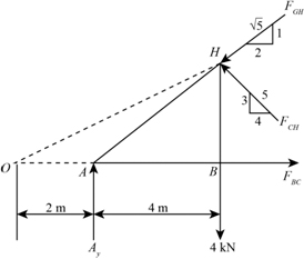
Here, ${F_{BC}}$ is the force in member BC, ${F_{GH}}$ is the force in member GH and ${F_{CH}}$ is the force in member CH.
We have the distance between point O and A is $d = 2\;{\rm{m}}$.
Step 6
Applying the moment of force equation about point H:
\[ - {A_y}{d_1} + {F_{BC}}{h_1} = 0\]Step 7
Substitute the known values in the equation:
\[\begin{array}{c} - \left( {{\rm{8}}{\rm{.25}}\;{\rm{kN}}} \right)\left( {{\rm{4}}\;{\rm{m}}} \right) + {F_{BC}}\left( {3\;{\rm{m}}} \right) = 0\\ {F_{BC}}\left( {{\rm{3}}\;{\rm{m}}} \right) = 33\;{\rm{kN}} \cdot {\rm{m}}\\ {F_{BC}} = 11\;{\rm{kN}} \end{array}\]Therefore, the force is tension in member BC.
Step 8
Applying the moment of force equation about point C:
\[{F_{GH}}\sin {\theta _1}\left( {{d_3} + {d_4} + d} \right) + {F_B}{d_1} - {A_y}\left( {{d_1} + {d_2}} \right) = 0\]…… (1)Step 9
According to the given diagram:
\[\sin {\theta _1} = \frac{1}{{\sqrt 5 }}\]Step 10
Substitute the known values in the equation (1):
\[\begin{array}{c} \left\{ \begin{array}{l} {F_{GH}}\left( {\frac{1}{{\sqrt 5 }}} \right)\left( {4\;{\rm{m}} + 4\;{\rm{m}} + \frac{{4\;{\rm{m}}}}{2}} \right) + \\ \left( {{\rm{4}}\;{\rm{kN}}} \right)\left( {{\rm{4}}\;{\rm{m}}} \right) - \left( {{\rm{8}}{\rm{.25}}\;{\rm{kN}}} \right)\left( {4\;{\rm{m}} + 4\;{\rm{m}}} \right) \end{array} \right\} = 0\\ {F_{GH}}\left( {\frac{1}{{\sqrt 5 }}} \right)\left( {{\rm{10}}\;{\rm{m}}} \right) = - 16\;{\rm{kN}} \cdot {\rm{m}} + 66\;{\rm{kN}} \cdot {\rm{m}}\\ {F_{GH}}\left( {4.47\;{\rm{m}}} \right) = 50\;{\rm{kN}} \cdot {\rm{m}}\\ {F_{GH}} = 11.2\;{\rm{kN}} \end{array}\]Therefore, the force is compression in member GH.
Step 11
Applying the moment of force equation about point O:
\[{F_{CH}}\sin {\theta _2}\left( {{d_3} + {d_4} + d} \right) + {A_y}d - {F_B}\left( {{d_1} + d} \right) = 0\]…… (2)Step 12
According to the given diagram:
\[\sin {\theta _2} = \frac{3}{5}\]Step 13
Substitute the known values in the equation (1):
\[\begin{array}{c} \left\{ \begin{array}{l} {F_{CH}}\left( {\frac{3}{5}} \right)\left( {4\;{\rm{m}} + 4\;{\rm{m}} + 2\;{\rm{m}}} \right) - \\ \left( {{\rm{8}}{\rm{.25}}\;{\rm{kN}}} \right)\left( {{\rm{2}}\;{\rm{m}}} \right) + \left( {{\rm{4}}\;{\rm{kN}}} \right)\left( {4\;{\rm{m}} + 2\;{\rm{m}}} \right) \end{array} \right\} = 0\\ {F_{CH}}\left( {\frac{3}{5}} \right)\left( {{\rm{10}}\;{\rm{m}}} \right) = 16.5\;{\rm{kN}} \cdot {\rm{m}} - 24\;{\rm{kN}} \cdot {\rm{m}}\\ {F_{CH}}\left( {6\;{\rm{m}}} \right) = - 7.5\;{\rm{kN}} \cdot {\rm{m}}\\ {F_{CH}} = - 1.25\;{\rm{kN}} \end{array}\]Therefore, the force is compression in member CH.
Step 14
The free body diagram of the point G is shown as:
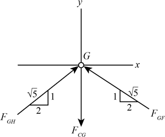
Here, ${F_{CG}}$ is the force in member CG, ${F_{GH}}$ is the force in member GH and ${F_{GF}}$ is the force in member GF.
Step 15
Applying the equilibrium force of equation along x-axis at point G:
\[\begin{array}{c} \sum {F_x} = 0\\ {F_{GH}}\cos {\theta _3} - {F_{GF}}\cos {\theta _4} = 0 \end{array}\]…… (3)Step 16
According to the given diagram:
\[\begin{array}{c} \cos {\theta _3} = \frac{2}{{\sqrt 5 }}\\ \cos {\theta _4} = \frac{2}{{\sqrt 5 }} \end{array}\]Step 17
Substitute the known values in the equation (3):
\[\begin{array}{c} \left( {11.2\;{\rm{kN}}} \right)\left( {\frac{2}{{\sqrt 5 }}} \right) - {F_{GF}}\left( {\frac{2}{{\sqrt 5 }}} \right) = 0\\ {F_{GF}}\left( {\frac{2}{{\sqrt 5 }}} \right) = \left( {{\rm{11}}{\rm{.2}}\;{\rm{kN}}} \right)\left( {\frac{2}{{\sqrt 5 }}} \right)\\ {F_{GF}} = 11.2\;{\rm{kN}} \end{array}\]Therefore, the force is tension in member GF.
Step 18
Applying the equilibrium force of equation along y-axis:
\[\begin{array}{c} \sum {F_y} = 0\\ 2{F_{GH}}\sin {\theta _3} - {F_{CG}} = 0 \end{array}\]Step 19
According to the given diagram:
\[\sin {\theta _3} = \frac{1}{{\sqrt 5 }}\]Step 20
Substitute the known values in the equation:
\[\begin{array}{c} 2\left( {11.2\;{\rm{kN}}} \right)\left( {\frac{1}{{\sqrt 5 }}} \right) - {F_{CG}} = 0\\ {F_{CG}} = \frac{{22.4\;{\rm{kN}}}}{{2.24}}\\ = 10\;{\rm{kN}} \end{array}\]Therefore, the force is tension in member CG.