Engineering Mechanics: Statics and Dynamics, 14th Edition
Authors: Russell C. Hibbeler
ISBN-13: 978-0133915426
See our solution for Question 46P from Chapter 7 from Hibbeler's Engineering Mechanics.
Problem 46P
Step-by-Step Solution
We are given the following data:
The magnitude of load is $P = 800\;{\rm{lb}}$.
The value of smaller distance is $a = 5\;{\rm{ft}}$.
The value of larger distance is $L = 12\;{\rm{ft}}$.
We are asked to draw the shear and moment diagrams for the shaft in terms of parameters shown in the figure.
Step 2
(a)
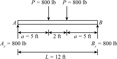
Consider two points $A$ and $B$ on the shaft.
We will draw the free-body diagram of the shaft.

Here, ${A_{\rm{x}}}$ is the horizontal force at point $A$, ${A_{\rm{y}}}$ is the vertical force at point $A$ and ${B_{\rm{y}}}$ is the vertical force at point $B$.
We will take the sum of the vertical forces in the $y$ direction and equate to zero to determine the force equation.
\[{A_{\rm{y}}} + {B_{\rm{y}}} = {P_1} + {P_2}\]Substitute all the known values in the above formula.
\[\begin{array}{c} {A_{\rm{y}}} + {B_{\rm{y}}} = P + P\\ = 2P \end{array}\]Step 3
We will take the sum of the moment about the point $A$ and equate to zero to determine the forces ${B_{\rm{y}}}$.
\[\begin{array}{c} \sum {{M_{\rm{A}}}} = 0\\ \left[ {\left( {{P_1}} \right)a + \left( {{P_2}} \right)\left( {L - a} \right) - \left( {{B_{\rm{y}}}} \right)\left( L \right)} \right] = 0 \end{array}\]Substitute all the known values in the above formula.
\[\begin{array}{c} \left[ {\left( {Pa} \right) + P\left( {L - a} \right) - \left( {{B_{\rm{y}}}} \right)\left( L \right)} \right] = 0\\ \left[ {PL - {B_{\rm{y}}}L} \right] = 0\\ {B_{\rm{y}}} = P \end{array}\]Substitute the value ${B_{\rm{y}}} = P$ in the equation ${A_{\rm{y}}} + {B_{\rm{y}}} = 2P$ to determine the force ${A_{\rm{y}}}$.
\[\begin{array}{c} {A_{\rm{y}}} + P = 2P\\ {A_{\rm{y}}} = \left( {2P - P} \right)\\ {A_{\rm{y}}} = P \end{array}\]Step 4
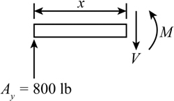
For $0 \le x \le a$
We will draw the free body diagram.
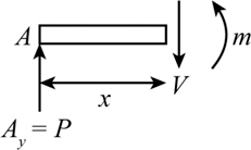
We will take the sum of the forces along the $y$ axis and equate to zero to determine the shear force $V$.
\[\begin{array}{c} \sum {{F_{\rm{y}}}} = 0\\ \left[ {{A_{\rm{y}}} - V} \right] = 0 \end{array}\]Substitute all the known values in the above equation.
\[\begin{array}{c} \left[ {P - V} \right] = 0\\ V = P \end{array}\]Step 5
We will take the sum of the moment and equate to zero to determine the moment $M$.
\[\begin{array}{c} \sum M = 0\\ M = Px \end{array}\] Step 6For $a < x < \left( {L - a} \right)$,
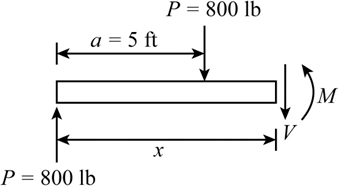
We will draw the free-body diagram.
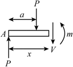
Here, $V$ represent the shear force, $M$ represent the moment at the right section of the shaft free-body diagram.
We will take the sum of the forces in the $y$ direction and equate to zero to determine the shear force $V$.
\[\begin{array}{c} \sum {{F_{\rm{y}}}} = 0\\ \left[ {V + P - P} \right] = 0\\ V = 0 \end{array}\] Step 7We will take the sum of the moment and equate to zero to determine the moment $M$.
\[\begin{array}{c} \sum M = 0\\ \left[ { - Px + P\left( {x - a} \right) + M} \right] = 0\\ \left[ { - Pa + M} \right] = 0\\ M = Pa \end{array}\] Step 8For $\left( {L - a} \right) < x \le L$,
We will draw the free-body diagram.
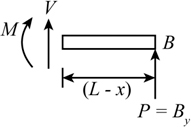
Here, $V$ represent the shear force and $M$ represent the moment at the right section of the shaft free-body diagram.
We will take the sum of the forces in the $y$ direction and equate to zero to determine the shear force $V$.
\[\begin{array}{c} \sum {{F_{\rm{y}}}} = 0\\ \left[ {{B_{\rm{y}}} + V} \right] = 0 \end{array}\]Substitute the known value in the above equation.
\[\begin{array}{c} \left[ {P + V} \right] = 0\\ V = - P \end{array}\]Step 9
We will take the sum of the moment and equate to zero to determine the moment $M$.
\[\begin{array}{c} \sum M = 0\\ \left[ { - M + P\left( {L - x} \right)} \right] = 0\\ M = P\left( {L - x} \right) \end{array}\]Finally we will draw the free-body diagram, shear force diagram and moment diagram of the shaft simultaneously.

Step 10
(b)
From the above calculations we will obtain the following values.
Substitute the value $P = 800\;{\rm{lb}}$ in the equation ${A_{\rm{y}}} = P$ and ${B_{\rm{y}}} = P$ to obtain the value of ${A_{\rm{y}}}$ and ${B_{\rm{y}}}$.
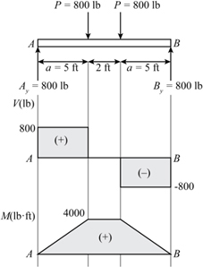
\[\begin{array}{c} {A_{\rm{y}}} = 800\;{\rm{lb}}\\ {B_{\rm{y}}} = 800\;{\rm{lb}} \end{array}\]We will draw the free-body diagram of the entire beam
For $0 \le x < \left( {5\;{\rm{ft}}} \right)$
We will draw the free-body diagram.
We will take the sum of the forces in the $y$ direction and equate to zero to determine the shear forces $V$.
\[\begin{array}{c} \sum {{F_{\rm{y}}}} = 0\\ \left[ {{A_{\rm{y}}} - V} \right] = 0 \end{array}\]Substitute all the known values in the above formula.
\[\begin{array}{c} \left[ {\left( {800\;{\rm{lb}}} \right) - V} \right] = 0\\ V = 800\;{\rm{lb}} \end{array}\] Step 12We will take the sum of the moment and equate to zero to determine the moment $M$.
\[\begin{array}{c} \sum M = 0\\ \left[ {\left( {{A_{\rm{y}}}} \right)\left( x \right) - M} \right] = 0 \end{array}\]Substitute all the known values in the above equation.
\[\begin{array}{c} \left[ {\left( {800\;{\rm{lb}}} \right)\left( x \right) - M} \right] = 0\\ M = \left( {800x} \right)\;{\rm{lb}} \cdot {\rm{ft}} \end{array}\]Step 13
For $\left( {5\;{\rm{ft}}} \right) < x < \left( {7\;{\rm{ft}}} \right)$,
We will draw the free-body diagram.
Here, $V$ represent the shear force and $M$ represent the moment at the right section of the shaft free-body diagram.
We will take the sum of the forces in the $y$ direction and equate to zero to determine the shear force $V$.
\[\begin{array}{c} \sum {{F_{\rm{y}}}} = 0\\ \left[ {P - P - V} \right] = 0 \end{array}\]Substitute the known value in the above equation.
\[\begin{array}{c} \left[ {\left( {800\;{\rm{lb}}} \right) - \left( {800\;{\rm{lb}}} \right) - V} \right] = 0\\ V = 0 \end{array}\]Step 14
We will take the sum of the moment and equate to zero to determine the moment $M$.
\[\begin{array}{c} \sum M = 0\\ \left[ { - \left( P \right)\left( x \right) + \left( P \right)\left( {x - a} \right) + M} \right] = 0 \end{array}\]Substitute the known value in the above equation.
\[\begin{array}{c} \left[ {\left( { - 800\;{\rm{lb}}} \right)\left( x \right) + \left( {800\;{\rm{lb}}} \right)\left( {x - 5\;{\rm{ft}}} \right) + M} \right] = 0\\ \left[ {\left( { - 4000\;{\rm{lb}} \cdot {\rm{ft}}} \right) + M} \right] = 0\\ M = 4000\;{\rm{lb}} \cdot {\rm{ft}} \end{array}\]Step 15
For $\;\left( {7\;{\rm{ft}}} \right) < x \le \left( {12\;{\rm{ft}}} \right)$,
We will draw the free-body diagram.
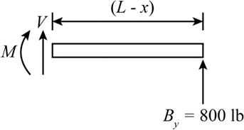
Here, $V$ represent the shear force and $M$ represent the moment at the right section of the shaft free-body diagram.
We will take the sum of the forces in the $y$ direction and equate to zero to determine the shear force $V$.
\[\begin{array}{c} \sum {{F_{\rm{y}}}} = 0\\ \left[ {V + {B_{\rm{y}}}} \right] = 0 \end{array}\]Substitute the known value in the above equation.
\[\begin{array}{c} \left[ {V + \left( {800\;{\rm{lb}}} \right)} \right] = 0\\ V = - 800\;{\rm{lb}} \end{array}\]Step 16
We will take the sum of the moment and equate to zero to determine the moment $M$.
\[\begin{array}{c} \sum M = 0\\ \left[ { - V\left( {L - x} \right) - M} \right] = 0 \end{array}\]Substitute the known value in the above equation.
\[\begin{array}{c} \left[ { - \left( { - 800\;{\rm{lb}}} \right)\left( {12\;{\rm{ft}}\; - x} \right) - M} \right] = 0\\ M = \left( {9600 - 800x} \right)\;{\rm{lb}} \cdot {\rm{ft}} \end{array}\]Finally we will draw the free-body diagram, shear force diagram and moment diagram of the shaft simultaneously.