Engineering Mechanics: Statics and Dynamics, 14th Edition
Authors: Russell C. Hibbeler
ISBN-13: 978-0133915426
See our solution for Question 79P from Chapter 7 from Hibbeler's Engineering Mechanics.
Problem 79P
Step-by-Step Solution
We are given the load $P = 100\;{\rm{lb/ft}}$, force $F = 200\;{\rm{lb}}$ and moment $M = 300\;{\rm{lb}} \cdot {\rm{ft}}$.
We are asked to draw the shear and moment diagrams.
Step 2
The reaction force on the load is calculated as:
\[R = P \times {d_1}\]Here, ${d_1}$ is the distance on which uniform distributed load is applied.
On plugging the values in the above relation, we get,
\[\begin{array}{l} R = \left( {100\;{\rm{lb/ft}}} \right) \times \left( {4\;{\rm{ft}}} \right)\\ R = 400\;{\rm{lb}} \end{array}\]The free body diagram of the beam is shown below:

The length between reaction force and point $A$ is ${d_2} = 2\;{\rm{ft}}$.
The length between force and point $A$ is ${d_3} = 1\;{\rm{ft}}$.
The length between force at $B$ and point $A$ is ${d_4} = 4\;{\rm{ft}}$.
To find the moment we will use the relation,
\[\begin{array}{c} \Sigma {M_A} = 0\\ M + R \times {d_2} - F \times {d_3} - {Y_B} \times {d_4} = 0 \end{array}\]On plugging the values in the above relation, we get,
\[\begin{array}{c} \Sigma {M_A} = 0\\ 300\;{\rm{lb}} \cdot {\rm{ft}} + 400\;{\rm{lb}} \times \left( {2\,{\rm{ft}}} \right) - 200\;{\rm{lb}} \times \left( {1\,{\rm{ft}}} \right) - {Y_B} \times \left( {4\,{\rm{ft}}} \right) = 0\\ {Y_B} = 225\;{\rm{lb}} \end{array}\]To find the force we will equate all the forces in horizontal direction by using relation,
\[\begin{array}{c} \Sigma {F_x} = 0\\ {X_A} = 0 \end{array}\]To find the force we will equate all the forces in vertical direction by using relation,
\[\begin{array}{c} \Sigma {F_y} = 0\\ {Y_A} - R - F + {Y_B} = 0 \end{array}\]On plugging the values in the above relation, we get,
\[\begin{array}{c} {Y_A} - 400\;{\rm{lb}} - 200\;{\rm{lb}} + 225\;{\rm{lb}} = 0\\ {Y_A} = 375\;{\rm{lb}} \end{array}\]Step 3
To find the shear force we will use the relation,
\[\begin{array}{l} {F_{x = 0 - 1}} = - F\\ {F_{x = 0 - 1}} = - 200\;{\rm{lb}} \end{array}\]To find the shear force at $1\;{\rm{ft}}$ we will use the relation,
\[\begin{array}{c} {F_{x = 1}} = {F_{x = 0 - 1}} + {Y_A}\\ {F_{x = 1}} = - 200\;{\rm{lb}} + 375\;{\rm{lb}}\\ {F_{x = 1}} = 175\;{\rm{lb}} \end{array}\]To find the shear force at $5\,{\rm{ft}}$ we will use the relation,
\[\begin{array}{c} {F_{x = 5}} = {F_{x = 1}} - R\\ {F_{x = 5}} = 175\;{\rm{lb}} - 400\;{\rm{lb}}\\ {F_{x = 5}} = - 225\;{\rm{lb}} \end{array}\]To find the shear force at $6\,{\rm{ft}}$ we will use the relation,
\[\begin{array}{l} {F_{5 - 6}} = {F_{x = 5}} + {Y_B}\\ {F_{5 - 6}} = - 225\;{\rm{lb}} + 225\;{\rm{lb}}\\ {F_{5 - 6}} = 0\;{\rm{lb}} \end{array}\]The location of zero shear force is calculated as:
\[\frac{x}{{{F_{x = 1}}}} = \frac{{{d_4}}}{{\left( {{Y_B} + {F_{x = 1}}} \right)}}\]On plugging the values in the above relation we get,
\[\begin{array}{c} \frac{x}{{175\;{\rm{lb}}}} = \frac{{4\;{\rm{ft}}}}{{\left( {175\;{\rm{lb}} + 225\;{\rm{lb}}} \right)}}\\ x = 1.75\;{\rm{ft}} \end{array}\]The shear force diagram is shown below:

Step 4
To find the bending moment we will use the relation,
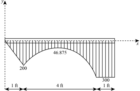
\[{M_{x = 0}} = 0\]To find the bending moment at $1\;{\rm{ft}}$ we will use the relation,
\[{M_{x = 1}} = - F \times {d_3}\]On plugging the values in the above relation we get,
\[\begin{array}{l} {M_{x = 1}} = - \left( {200\;{\rm{lb}}} \right) \times \left( {1\;{\rm{ft}}} \right)\\ {M_{x = 1}} = - \;200\;{\rm{lb}} \cdot {\rm{ft}} \end{array}\]To find the bending moment at $2.75\;{\rm{ft}}$ we will use the relation,
\[{M_{x = 2.75}} = {M_{x = 1}} + \frac{1}{2} \times {F_{x = 1}} \times x\]On plugging the values in the above relation we get,
\[\begin{array}{l} {M_{x = 2.75}} = - \;200\;{\rm{lb}} \cdot {\rm{ft}} + \frac{1}{2} \times \left( {175\;{\rm{lb}}} \right) \times \left( {1.75\;{\rm{ft}}} \right)\\ {M_{x = 2.75}} = - \;46.875\;{\rm{lb}} \cdot {\rm{ft}} \end{array}\]To find the bending moment at $5\;{\rm{ft}}$ we will use the relation,
\[{M_{x = 5}} = {M_{x = 2.75}} + \frac{1}{2} \times {F_{x = 5}} \times \left( {{d_4} - x} \right)\]On plugging the values in the above relation we get,
\[\begin{array}{l} {M_{x = 5}} = - \;46.875\;{\rm{lb}} \cdot {\rm{ft}} - \frac{1}{2} \times 225\;{\rm{lb}} \times \left( {4\;{\rm{ft}} - 1.75\;{\rm{ft}}} \right)\\ {M_{x = 5}} = - \;300\;{\rm{lb}} \cdot {\rm{ft}} \end{array}\]To find the bending moment at $6\;{\rm{ft}}$ we will use the relation,
\[{M_{x = 6}} = {M_{x = 5}} + M\]On plugging the values in the above relation we get,
\[\begin{array}{l} {M_{x = 6}} = - \;300\;{\rm{lb}} \cdot {\rm{ft}} + \;300\;{\rm{lb}} \cdot {\rm{ft}}\\ {M_{x = 6}} = 0\;{\rm{lb}} \cdot {\rm{ft}} \end{array}\]The bending moment diagram is shown below: