Engineering Mechanics: Statics and Dynamics, 14th Edition
Authors: Russell C. Hibbeler
ISBN-13: 978-0133915426
See our solution for Question 63P from Chapter 8 from Hibbeler's Engineering Mechanics.
Problem 63P
Step-by-Step Solution
We are given that the distance of spring compressed is $x = 175\;{\rm{mm}}$, the stiffness constant of the spring is $k = 15\;{\rm{kN/m}}$, the coefficient of static friction between all surfaces is ${\mu _s} = 0.35$ and the angle made by wedge with the horizontal is $\theta = 10^\circ $.
We are asked to calculate the minimum force required to move wedge.
Step 2
The free body diagram of the block B is shown as:
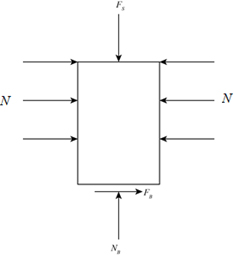
Here, ${F_s}$ is the spring force acting on block B, $N$ is the normal forces acting on the sides of block, ${F_B}$ is the frictional force acting on block B and ${N_B}$ is the normal force acting on block B.
Step 3
According to free body diagram, the net force acting on block B along y-axis is given as:
\[\begin{array}{c} \sum {F_y} = 0\\ - {F_s} + {N_B} = 0 \end{array}\]…… (1)Step 4
To calculate the spring force acting on block B we use the formula:
\[{F_s} = kx\]Step 5
Substitute the known value in the equation (1):
\[\begin{array}{c} - kx + {N_B} = 0\\ {N_B} = kx \end{array}\]Step 6
Substitute the known values in the equation:
\[\begin{array}{c} {N_B} = \left( {{\rm{15}}\;{\rm{kN/m}}} \right)\left( {{\rm{175}}\;{\rm{mm}}} \right)\left( {\frac{{{{10}^{ - 3}}\;{\rm{m}}}}{{1\;{\rm{mm}}}}} \right)\\ = 2.625\;{\rm{kN}} \end{array}\]Step 7
The free body diagram of the wedge is shown as:
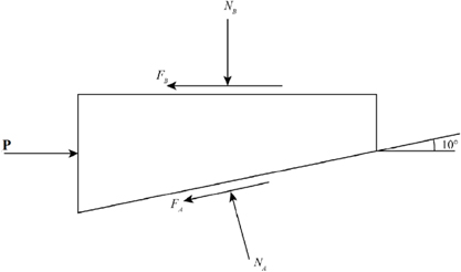
Here, ${\bf{P}}$ is the applied force, ${F_A}$ is the vertical force acting on bottom surface and ${N_A}$ is the normal force acting on bottom surface.
Step 8
According to free body diagram, the net force acting on wedge along y-axis is given as:
\[\begin{array}{c} \sum {F_y} = 0\\ {N_A}\cos \theta - {F_A}\sin \theta - {N_B} = 0 \end{array}\]…… (2)Step 9
To calculate the frictional force acting on bottom surface we use the formula:
\[{F_A} = {\mu _s}{N_A}\]Step 10
Substitute the known value in equation (2):
\[\begin{array}{c} {N_A}\cos \theta - {\mu _s}{N_A}\sin \theta - {N_B} = 0\\ {N_A}\left( {\cos \theta - {\mu _s}\sin \theta } \right) = {N_B}\\ {N_A} = \frac{{{N_B}}}{{\left( {\cos \theta - {\mu _s}\sin \theta } \right)}} \end{array}\]Step 11
Substitute the known values in the equation:
\[\begin{array}{c} {N_A} = \frac{{\left( {2.625\;{\rm{kN}}} \right)}}{{\left( {\cos 10^\circ - \left( {0.35} \right)\sin 10^\circ } \right)}}\\ = \frac{{\left( {2.625\;{\rm{kN}}} \right)}}{{\left( {0.985 - \left( {0.35} \right)\left( {0.175} \right)} \right)}}\\ = \frac{{\left( {2.625\;{\rm{kN}}} \right)}}{{\left( {0.924} \right)}}\\ = 2.841\,{\rm{kN}} \end{array}\]Step 12
According to free body diagram, the net force acting on wedge along x-axis is given as:
\[\begin{array}{c} \sum {F_x} = 0\\ {\bf{P}} - {F_B} - {F_A}\cos \theta - {N_A}\sin \theta = 0 \end{array}\]…… (3)Step 13
To calculate the spring force acting on top surface we use the formula:
\[{F_B} = {\mu _s}{N_B}\]Step 14
Substitute the known value in equation (3):
\[{\bf{P}} - {\mu _s}{N_B} - {\mu _s}{N_A}\cos \theta - {N_A}\sin \theta = 0\]Step 15
Substitute the known values in the equation:
\[\begin{array}{c} \left\{ \begin{array}{l} {\bf{P}} - \left( {0.35} \right)\left( {2.625\;{\rm{kN}}} \right)\\ - \left( {0.35} \right)\left( {2.841\;{\rm{kN}}} \right)\cos 10^\circ \\ - \left( {2.841\;{\rm{kN}}} \right)\sin 10^\circ \end{array} \right\} = 0\\ {\bf{P}} = 0.919\;{\rm{kN}} + 0.979\;{\rm{kN}} + 0.497\;{\rm{kN}}\\ = 2.39\;{\rm{kN}} \end{array}\]